WiPy 3.0
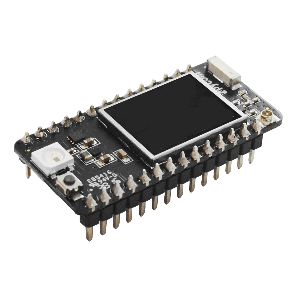
Please Note: We have removed the labels from the pictures in the documentation due to inconsistencies with label orientation. The LED must be aligned above the USB socket when inserting or removing a development board from an expansion board/Pytrack/Pysense/Pyscan.
Store: Buy Here
Getting Started: Click Here
Datasheet
The datasheet of the WiPy3 is available as a PDF File.
Pinout
The pinout of the WiPy3 is available as a PDF File.
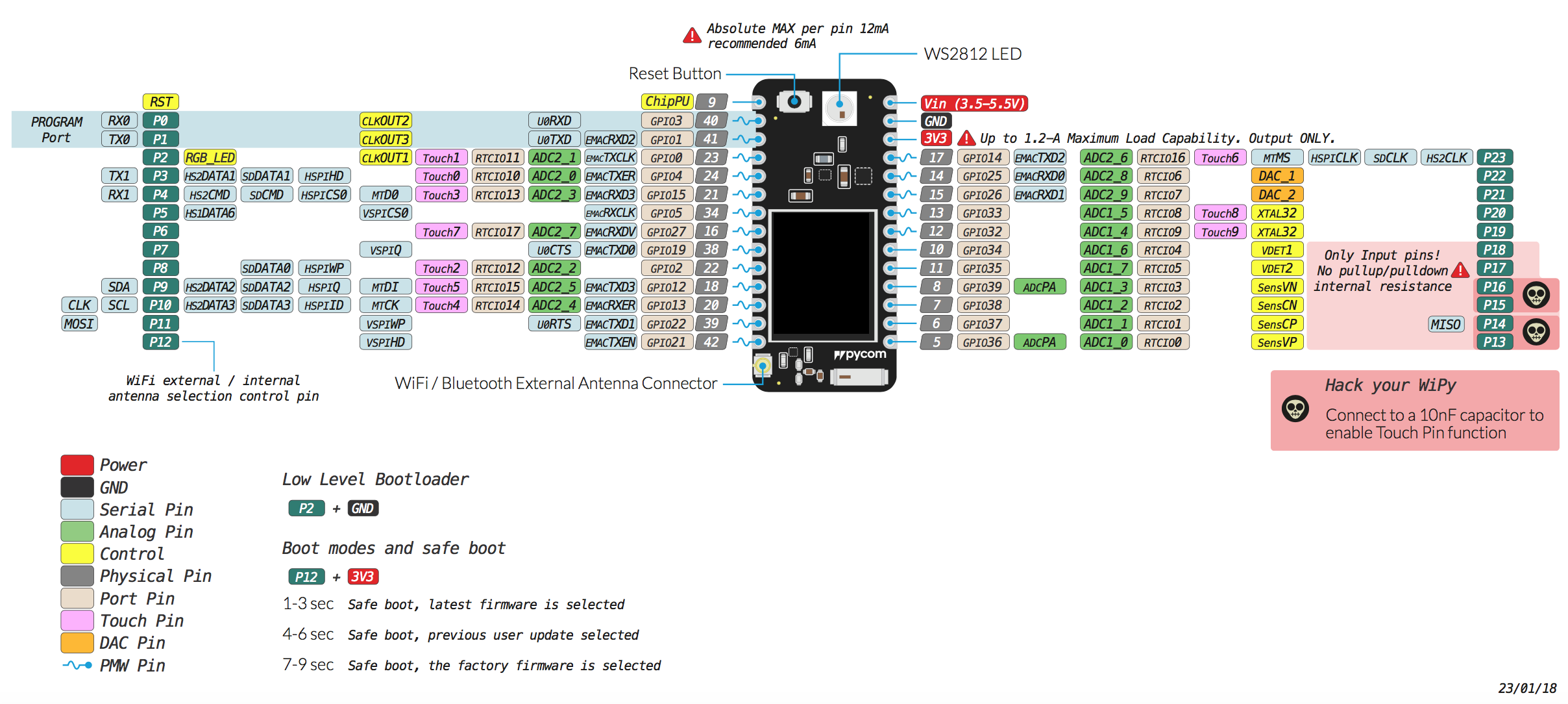
Please note that the PIN assignments for UART1 (TX1/RX1), SPI (CLK, MOSI, MISO) and I2C (SDA, SCL) are defaults and can be changed in Software.
Differences from WiPy 2.0
- Deep sleep current draw fixed, now only 19.7µA
- Upgraded RAM from 512KB to 4MB
- Upgraded External FLASH from 4MB to 8MB
- Antenna select pin moved from GPIO16 to GPIO21 (P12)
Notes
WiFi
By default, upon boot the WiPy3 will create a WiFi access point with the SSID wipy-wlan-XXXX, where XXXX is a random 4-digit number, and the password www.pycom.io.
The RF switch that selects between the on-board and external antenna is connected to P12, for this reason using P12 should be avoided unless WiFi is disabled in your application.
Power
The Vin pin on the WiPy3 can be supplied with a voltage ranging from 3.5v to 5.5v. The 3.3v pin on the other hand is output only, and must not be used to feed power into the WiPy3, otherwise the on-board regulator will be damaged.
Tutorials
Tutorials on how to the WiPy3 module can be found in the examples section of this documentation. The following tutorials might be of specific interest for the WiPy3: